
Dyno sheet for the 641" deal with a few pics..
Page 2 of 2 •  1, 2
1, 2
Re: Dyno sheet for the 641" deal with a few pics..
![]() Lem Evans September 13th 2011, 9:26 pm
Lem Evans September 13th 2011, 9:26 pm
1,212 Hp at 7,400 RPM. It was a recyeled thing but a player never the less.
Did I mention that it was a carb & gas deal......i'm not sure about the color of the oil
Lem Evans- Posts : 7445
Join date : 2008-12-03
Location : Livermore , Ky -

Re: Dyno sheet for the 641" deal with a few pics..
![]() David Willingham September 13th 2011, 9:32 pm
David Willingham September 13th 2011, 9:32 pm
David Willingham- BBF CONTRIBUTOR

- Posts : 495
Join date : 2008-12-02
Age : 51
Location : Blountsville, AL
Re: Dyno sheet for the 641" deal with a few pics..
![]() David Willingham September 13th 2011, 9:41 pm
David Willingham September 13th 2011, 9:41 pm
David Willingham- BBF CONTRIBUTOR
- Posts : 495
Join date : 2008-12-02
Age : 51
Location : Blountsville, AL
Re: Dyno sheet for the 641" deal with a few pics..
![]() Lem Evans September 13th 2011, 10:05 pm
Lem Evans September 13th 2011, 10:05 pm
David Willingham wrote:Lem, great job as always.
One Phillip's projects.....
Lem Evans- Posts : 7445
Join date : 2008-12-03
Location : Livermore , Ky -
Re: Dyno sheet for the 641" deal with a few pics..
![]() bruno September 14th 2011, 6:06 am
bruno September 14th 2011, 6:06 am
David Willingham wrote:Not yet. My business is having a hard time right now and I don't really have any money to spend until I can get back on my feet.
i hope things get better for you David
_________________
coming soon x275 build .........
thanks to all my sponsors :
www.OakleyMotorsports.com
www.Induction-Solutions.com
www.bfevansraceparts.com
www.ultimateconverter.com
www.keithfulpmotorsports.com

bruno- Moderator
- Posts : 10873
Join date : 2008-12-02
Age : 51
Location : MILLBROOK , AL. -
Re: Dyno sheet for the 641" deal with a few pics..
![]() LivermoreDave September 14th 2011, 8:33 am
LivermoreDave September 14th 2011, 8:33 am
Now, first let me say, I'm not a person with knowledge of such adventures as yours, I know very little relative to "hands-on" performance, but I do have a bit to add (comment) about the injector location and as you mentioned the fuel disturbing the air flow.
Several years ago Charlie allowed me to travel with him to Jeff Jones shop in Indiana. I was amazed at the opportunity to the "feel-free" attitude Mr. Jones offered Charlie and myself to look around un-escorted. Similar as I was when Charlie and I visited you at your former employer! Mr Jones explained to Charlie and myself when I asked of the injectors located into the cylinder head protruding into the intake valve pocket (bowl). He explained as you mentioned after switching from methanol to gasoline, the volume of methanol it takes to provide the proper air/fuel mix "cluttered" the ports ability to retain air flow when injected high in the intake. Therefore a nozzle was inserted at the beginning of the intake simply for low speed operation and delivered a small portion (%) of the total volume of fuel. The larger (% of volume) was delivered into the cylinder head nozzle.This approach offered 50 extra horsepower to Mr. Jones' application.
Another note as a few have mentioned, the height of the nozzle location. And again, I'm just asking, it seems the nozzle at a lower point would offer a bit more direct spray into the intake valve bowl, although that runner is very straight, I'm just wondering which would work the best in an application such as yours. Does the higher location of the nozzle offer more torque or is it simply a starting point?
Thanks for allowing me to ramble.
Best regards,
Dave.
LivermoreDave- Posts : 972
Join date : 2009-09-27
Location : North of the Equator.
Re: Dyno sheet for the 641" deal with a few pics..
![]() David Willingham September 14th 2011, 10:56 am
David Willingham September 14th 2011, 10:56 am
As far as nozzle placement goes, I look to folks that know more than I do and that is why the Holmes intake and the high nozzle placement. I didn't know the intake was such a bad deal until it was too late to get it swapped before the dyno. The intake is wrong and I think that is one of the reasons it's down on power. I also think the nozzles need to be as close to the head as possible, if only one set is used. The reason one person wanted them high was to cool the charge, but I think it cost power due to air displacement. This person still thinks they need to be up there, but he is now alone in his opinion. I think I will get around to try nozzles in the head someday and if I do, the upper nozzles will be as high as possible. They will be all EFI and controlled with this new MFI computer, which was modifed recently to allow any percentage of fuel to go to either stage of injectors. I can make the upper injectors flow whatever I want and the lowers whatever I want. I can start out with either stage and ramp in the other stage if I want. I also can trim any individual injector if I need to.The ignition works the same way. I can tailor the timing for each cylinder if there is ever the need.
Anyway, all I need now is the biz to pick up so I have more funds to play with. First order of business is to get a better intake on there to get the peak up to 72-7500 as I think the truck needs all the top end charge it can get to fight the aero problem it's going to encounter at 140+. Lem suggested I may want to get a new block so I can run water and I think I will do that next year.
David Willingham- BBF CONTRIBUTOR
- Posts : 495
Join date : 2008-12-02
Age : 51
Location : Blountsville, AL
Re: Dyno sheet for the 641" deal with a few pics..
![]() LETHAL_DOSE September 14th 2011, 1:10 pm
LETHAL_DOSE September 14th 2011, 1:10 pm

LETHAL_DOSE- Posts : 62
Join date : 2009-09-30
Age : 49
Location : Columbia City, Indiana
Re: Dyno sheet for the 641" deal with a few pics..
![]() David Willingham September 14th 2011, 3:31 pm
David Willingham September 14th 2011, 3:31 pm
Also want to add that you may have to weld a sleeve in the head to seal up the water jacket. The heat from that may draw the seat and cause some issues. That is why i haven't done mine yet. I have to be prepared to deal with re-cutting the valve seat and make sure the seat pocket doesn't get messed up.
Last edited by David Willingham on September 15th 2011, 10:40 am; edited 1 time in total
David Willingham- BBF CONTRIBUTOR
- Posts : 495
Join date : 2008-12-02
Age : 51
Location : Blountsville, AL
Re: Dyno sheet for the 641" deal with a few pics..
![]() cool40 September 14th 2011, 9:33 pm
cool40 September 14th 2011, 9:33 pm

cool40- BBF CONTRIBUTOR
- Posts : 7308
Join date : 2009-08-31
Age : 53
Location : on the 1/8 mile dyno
Re: Dyno sheet for the 641" deal with a few pics..
![]() LivermoreDave September 14th 2011, 9:58 pm
LivermoreDave September 14th 2011, 9:58 pm
A bit of good reading by Mr.Duttweiler in an issue of Hot Rod Magazine.
In a perfect world, nozzle location should be as parallel to the airflow stream as possible. The nozzle angle in relation to the airflow stream is termed the "intercept angle." According to Strader, the intercept angle should "not be more than 45 degrees, although it can be less." Maintaining the proper intercept angle generally helps low-speed driveability and may also improve performance throughout the engine's operating band. The lower the inlet airspeed at idle, the more critical it is to maintain the ideal intercept angle. Idle vacuum correlates well with inlet airspeed-if you have 14-18 inches Hg of vacuum at idle as read on a vacuum gauge, maintaining the proper intercept angle is not as much of an issue in terms of driveability, although there still could be some emissions ramifications.
Two Duttweiler sheetmetal intakes: A 1,600hp Buick V-6 high-rpm drag-race motor responded well to a high injector location (left). Compared with the manifold in the big photo at right, Duttweiler 's previous-generation Chevy V-8 intake (above right) had 1/4-inch longer runners and lower-mounted injectors. The reason for the change was improved fuel atomization at 10,000 rpm.So much for injector angle-what about injector placement? Should it be closer to the valve (downstream, near the cylinder head) or closer to the air meter (upstream, toward the top of the inlet runner)? It depends on the engine and application. A stocker is primarily concerned with idle quality, low emissions, fuel mileage, and engine-compartment packaging constraints. On a stocker, fuel-injector capacity (rated in lb/hr) is low (compared with a race engine), while inlet-runner velocity and low-speed vacuum are high. The small-capacity nozzle develops a good spray pattern that disperses uniformly within the incoming air stream. With good atomization, the nozzle can be located downstream, close to the valve. Small injectors don't have a lot of fuel to waste, so targeting the spray toward the back side of the valve ensures that the available fuel is used most efficiently. On the other hand, in theory, high-idle vacuum generated by mild stock engines permits placing the injector farther upstream without significant low-speed driveability degradation. In the end, OEM-style downstream injector placement simplifies system packaging and makes it easier to mount the fuel rails.
Everything changes with really large injectors (over 96 lb/hr). High-capacity injectors generate a relatively poor spray pattern with a large fuel-droplet size. As Duttweiler puts it: "You're practically just spraying raw liquid. If you put a big injector too close to the valve, there's not enough time for the fuel to mix with the air." Large injectors would most likely be used in large-displacement or high-rpm engines with lumpy cams. High rpm translates into less time between injector firing pulses, lumpy cams generate poor vacuum, and the typically large-volume inlet runners needed to feed all those cubes generally mean lower air velocity downstairs. Obviously, all this adversely affects proper fuel atomization. Moving the injector farther away from the valve allows more time for the air/fuel to atomize properly and remain in suspension when air velocity comes up at high rpm. This should improve peak power but-because of poor low-rpm velocity-at the expense of idle quality (there's no free lunch).
Looking at some real-world examples, Strader reports that on a 1,000hp engine, the injectors were originally located 7 inches back from the valves. Doubling this distance to 14 inches was worth 50 hp on top, a 5 percent gain-but "it wouldn't idle below 1,600 rpm." For an even more extreme example, consider the injector placement on today's 15,000-rpm Formula I engines. The injectors, wiring harness, and fuel-distribution rails are located topside, even inside the manifold plenum area, so they can maintain the proper intercept angle.
In the real world, mass-produced aftermarket cast-aluminum manifolds have the bosses added as an afterthought to a preexisting design. The placement is more for convenience than for best engineering practice-the available packaging architecture (including fuel-rail mounting and clearance) to a large extent dictates the nozzle location. A decent compromise for a hot-rod engine is to locate the nozzle about 1-2 inches upstream from the manifold flange to give atomization a chance, positioning the fuel rail at the best angle you can get away with and still package the harness and fuel rails. As Duttweiler puts it: "If you aim the injector more toward the valve, the fuel rail usually hits the plenum" on a converted classic V-8 carburetor-style intake. Note that at the OEM level, the trend on today's new-tech V-8 engine designs is to make them wider than a similar-displacement, old-school, classic engine. The included valve angle in some of the new late-models is nearly straight up and down in relation to the bore. That means the runners are also near vertical, which in turn allows mounting the injectors more vertically to provide room for the fuel rails and wiring harness while still maintaining a good intercept angle to the runner.
Duttweiler Performance
Saticoy, CA
805/647-5732
EFI University
Murrieta, CA
Read more: http://www.hotrod.com/pitstop/hrdp_0704_pitstop_fuel_injector_location/#ixzz1Xywbtxyh
LivermoreDave- Posts : 972
Join date : 2009-09-27
Location : North of the Equator.
Re: Dyno sheet for the 641" deal with a few pics..
![]() LETHAL_DOSE September 15th 2011, 10:03 am
LETHAL_DOSE September 15th 2011, 10:03 am
LETHAL_DOSE- Posts : 62
Join date : 2009-09-30
Age : 49
Location : Columbia City, Indiana
Re: Dyno sheet for the 641" deal with a few pics..
![]() David Willingham September 16th 2011, 1:02 pm
David Willingham September 16th 2011, 1:02 pm
David Willingham- BBF CONTRIBUTOR
- Posts : 495
Join date : 2008-12-02
Age : 51
Location : Blountsville, AL
Re: Dyno sheet for the 641" deal with a few pics..
![]() bruno March 24th 2012, 5:07 am
bruno March 24th 2012, 5:07 am
_________________
coming soon x275 build .........
thanks to all my sponsors :
www.OakleyMotorsports.com
www.Induction-Solutions.com
www.bfevansraceparts.com
www.ultimateconverter.com
www.keithfulpmotorsports.com
bruno- Moderator
- Posts : 10873
Join date : 2008-12-02
Age : 51
Location : MILLBROOK , AL. -
Re: Dyno sheet for the 641" deal with a few pics..
![]() David Willingham March 24th 2012, 6:40 pm
David Willingham March 24th 2012, 6:40 pm
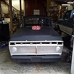
Not much on the engine. That will be a 2012-2013 winter project after the truck and driver have proven themselves on the track. I haven't worked on it in 4-5 months because of trying to get the biz back to making money. The last thing I was working on was the wiring. I wanted to get it running and moving around and then finish all the loose ends and get it painted. Here are some pics as it sits collecting dust.


David Willingham- BBF CONTRIBUTOR
- Posts : 495
Join date : 2008-12-02
Age : 51
Location : Blountsville, AL
Re: Dyno sheet for the 641" deal with a few pics..
![]() norm March 25th 2012, 8:10 am
norm March 25th 2012, 8:10 am

norm- Posts : 257
Join date : 2009-08-06
Location : michigan
Re: Dyno sheet for the 641" deal with a few pics..
![]() David Willingham March 25th 2012, 1:12 pm
David Willingham March 25th 2012, 1:12 pm
David Willingham- BBF CONTRIBUTOR
- Posts : 495
Join date : 2008-12-02
Age : 51
Location : Blountsville, AL

10SHOTS- Posts : 587
Join date : 2010-11-26
Age : 47
Location : Brookhaven MS 39601
Re: Dyno sheet for the 641" deal with a few pics..
![]() David Willingham March 26th 2012, 10:43 am
David Willingham March 26th 2012, 10:43 am
David Willingham- BBF CONTRIBUTOR
- Posts : 495
Join date : 2008-12-02
Age : 51
Location : Blountsville, AL
Re: Dyno sheet for the 641" deal with a few pics..
![]() dtimmer April 17th 2012, 2:45 pm
dtimmer April 17th 2012, 2:45 pm
dtimmer- Posts : 224
Join date : 2009-08-23
Age : 38
Location : Grand Rapids, MI -
Page 2 of 2 • 1, 2
» 606 A460
» Brett Powells dyno sheet
» Kaase dyno sheet, can't read it.
» Dyno results: A headed 557 on 91 octane pump gas. DYNO UPDATE page 6
|
|
|