Tig welding appearance ??
Page 1 of 2 • 1, 2 ![]()

Tig welding appearance ??
![]() TravisRice September 25th 2010, 12:56 pm
TravisRice September 25th 2010, 12:56 pm
Travis
TravisRice- BBF CONTRIBUTOR

- Posts : 1192
Join date : 2009-02-07
Re: Tig welding appearance ??
![]() f250mike September 25th 2010, 1:40 pm
f250mike September 25th 2010, 1:40 pm
Sometimes I'll go over my welds again without filler rod to give a flatter smooth look.
Sometimes just a little higher amperage does the trick for me.
Also try using 1/16" tunsten with the 1/16" filler rod.
mike
f250mike- Posts : 628
Join date : 2009-03-28
Age : 59
Location : Rensselaer, Indiana
Re: Tig welding appearance ??
![]() KY JELLY September 25th 2010, 2:35 pm
KY JELLY September 25th 2010, 2:35 pm
On a side note got the pump yesterday thanks

KY JELLY- Posts : 1530
Join date : 2008-12-03
Re: Tig welding appearance ??
![]() res0rli9 September 25th 2010, 2:53 pm
res0rli9 September 25th 2010, 2:53 pm
http://www.weldingtipsandtricks.com/pulse-tig.html
res0rli9- BBF CONTRIBUTOR
- Posts : 3351
Join date : 2008-12-02
Age : 74
Location : sarasota FL.
Re: Tig welding appearance ??
![]() TravisRice September 25th 2010, 3:44 pm
TravisRice September 25th 2010, 3:44 pm
I bought a new Miller 200 squarewave with the pulser option. It welds very nice for what I want to do with it. Hoping I can get the 4130 tubing to look as if it is fused together.
Glad the S-10 smog pump arrived safely.
TravisRice- BBF CONTRIBUTOR
- Posts : 1192
Join date : 2009-02-07
Re: Tig welding appearance ??
![]() TravisRice September 25th 2010, 3:56 pm
TravisRice September 25th 2010, 3:56 pm


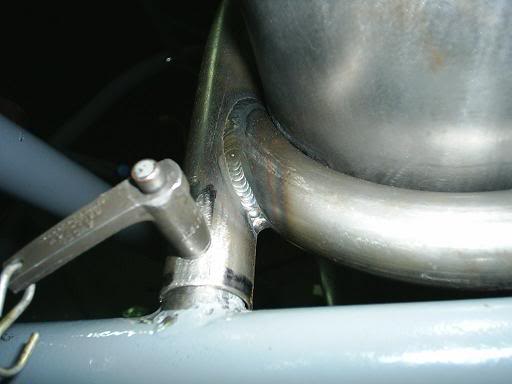
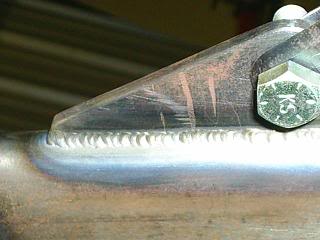
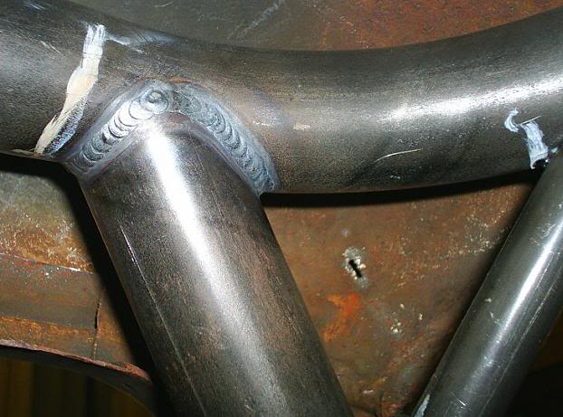
Here are a few of the welds on my car that I did that tured out OK. All of them look fine just a little fat in width, not built up in hieght just a little wide for my taste. JMO.
TravisRice- BBF CONTRIBUTOR
- Posts : 1192
Join date : 2009-02-07
Re: Tig welding appearance ??
![]() richter69 September 25th 2010, 5:04 pm
richter69 September 25th 2010, 5:04 pm

richter69- Posts : 13649
Join date : 2008-12-02
Age : 53
Location : In the winners circle
Re: Tig welding appearance ??
![]() f250mike September 25th 2010, 7:53 pm
f250mike September 25th 2010, 7:53 pm
Your welds look good, maybe a bit too much filler.
Go over them again with the torch and you should be able to get close to the look you want.
Try the 1/16" tungsten and see if that works for you. You will have a narrower weld and use less filler.
I use .035" filler rod on parts sometimes at work. You could try using some wire from your mig.
Play around on some scrap tube. You'll get it the way you want,
mike
f250mike- Posts : 628
Join date : 2009-03-28
Age : 59
Location : Rensselaer, Indiana
Re: Tig welding appearance ??
![]() DILLIGASDAVE September 26th 2010, 10:58 am
DILLIGASDAVE September 26th 2010, 10:58 am
The stack of dimes look is usually achieved (for me anyway) by waiting a little longer while forming the current puddle crater, causing it to get a little deeper before adding the filler rod. Then when I finally fill the puddle crater I slightly over fill it. Then when advancing the puddle & forming the next crater some of the excess filler is drug along & becomes part of the next new crater/puddle. I guess one way to think about the two puddles is with the stack of dimes puddle your dragging the puddle along at it's leading edge by digging a deep hole & filling it over & over (more filler each "dip", but fewer total "dips" overall). And the smooth puddle is more like pushing the already half filled puddle along (less filler each "dip" but using more total "dips" overall).
As for going back over a finished "stack of dimes" weld with just the Tig torch (& no filler rod) to smooth it out......it's usually OK on non-structural (sheetmetal & such) but I wouldn't do it on anything structural (roll cage, frame, etc).
As for the "correct" width of a given Tig puddle, it again can depend on the thickness of the parent material & the design/fit of the weld joint. Most times I end up with a puddle width that is usually thought of as being on the wider side of the "normal" width range. But then I honestly do believe that way too many people shoot for a Tig weld width that's really way too narrow (and thus less weld heat/penetration) for a given materials thickness. In my opinion too many people try to achieve the super narrow Tig puddle on the "thicker" cage material (.083" cm to .118" ms) that is really a more "correct" puddle width for a piece of thinner .058" to .065" cage material.
Here are some examples of my welds.........
'moly......


& HREW mild steel.......

As you can see, my puddle widths are generally on the wider side of the range (most of the time anyway) for a given material thickness. But thats just the way I have done them for years. It should be noted that my puddle widths for the thicker wall cm vs ms tubing (.083 moly vs .134 wall ms) are still of a similar width because the .134 wall ms tubing usually gets a looser joint fit (to aid the weld heat/penetration) so the ms puddle width doesn't end up being super wide.

DILLIGASDAVE- Posts : 2262
Join date : 2009-08-08
Location : Texas. pronounced "texASS"
Re: Tig welding appearance ??
![]() badnotch September 26th 2010, 12:10 pm
badnotch September 26th 2010, 12:10 pm
badnotch- Posts : 514
Join date : 2009-08-16
Age : 55
Location : akron-ohio -

Re: Tig welding appearance ??
![]() badnotch September 26th 2010, 12:13 pm
badnotch September 26th 2010, 12:13 pm

Most welders, even novices, are familiar with the traditional components of a GTAW torch-nozzles, collets and collet bodies, back caps and tungsten-but the gas lens may be more of a mystery. Because gas lenses are often reserved for use on high performance, specialty alloys or low-access joints and tend to cost more than other components, not every welder uses them. However, gas lenses can also be used on general-purpose applications and have a definite place among repair or fabrication shops, and even in the home hobbyist's garage.
Like other GTAW components, choosing the right gas lens, whether for a professional or hobby application, depends on the material to be welded, amperage requirements, joint configurations and tungsten size. It also depends on the type of GTAW torch being used-air- or water-cooled-but in both cases, the addition of a gas lens can provide definite benefits in GTAW welding performance.
What is a Gas Lens?
A gas lens replaces the collet body that is standard in a GTAW torch. In conjunction with a collet, it helps hold the tungsten in place and creates the electrical contact necessary for proper current transfer. It also serves a much more important function: it improves shielding gas coverage and joint accessibility.
A typical gas lens is composed of a copper and/or brass body with layered mesh screens of steel/stainless steel (stainless steel offers greater durability and resistance to rust and corrosion than steel) that helps evenly distribute the shielding gas around the tungsten and along the weld puddle and arc. Gas lenses can be used with all shielding gases and are available for both air- and water-cooled GTAW torches.
The most durable-but also the more expensive gas lenses-feature an engineered porous filter media (Figure 1) that improves laminar flow compared to conventional designs. Other gas lenses, such as those composed entirely of brass and with multiple screens (Figure 2), can serve the welding purposes of less demanding applications, but they can be less conductive and could hinder gas flow after multiple uses.
Figure 1. Some higher-priced gas lenses use a porous filter media to improve gas flow and extend product life.
Gas Lenses Offer Distinct Benefits
Gas lenses reduce shielding gas turbulence and provide longer, undisturbed laminar flow of the gas to the weld pool. The gas lens also allows the welder to move the nozzle further away from the joint and extend the tungsten electrode past the nozzle by one inch or more(1). This extension helps minimize tungsten inclusions and improves visibility of the arc and the weld puddle without sacrificing shielding gas coverage, especially on joints with limited access.
Gas lenses are specifically helpful when GTAW welding on alloys that are highly reactive to atmospheric contaminants or on materials used in high temperature applications, as poor gas coverage on these alloys can lead to porosity and material degradation, which may negatively impact the weld's strength. The gas coverage provided by gas lenses also helps prevent oxygen contamination on materials such as stainless steel, titanium and aluminum by minimizing weld discontinuities. In more basic GTAW applications, such as on steel, gas lenses simply improve shielding gas coverage to ensure more consistent welding performance.
The ability to stick the electrode out further (thanks to the laminar flow created by the gas lens) is also a major benefit of gas lenses. This additional electrode extension provides better visibility of the joint and arc, and can improve a welder's ability to lay a proper weld in critical applications and/or hard-to-reach areas such as "T", "K" and "Y" joints.
In some applications, a gas lens can reduce shielding gas consumption, but welders should not use gas lenses solely for this purpose. With all things being equal (amperage, torch-to-work distance and tungsten extension, for example), the laminar flow provided by the screens in gas lenses creates a wider, more even gas coverage area using equal (as in a non-gas lens application) or lesser (three to five cubic feet per hour less) amounts of gas.
Gas Lens Size Selection
Gas lenses come in a number of sizes for both air- and water-cooled torches. The type of gas lens a welder chooses for a given application will depend first and foremost on the type of front-end parts (10N or 13N) required for a given torch. A welder also needs to assess the amperage requirements (and therefore, tungsten size) for the material being welded, along with the joint configuration and amount of joint access. For example, lower amperage applications on non-reactive materials require a different type of gas lens than higher amperage applications on specialty and/or reactive materials.
Gas lenses for 10N series front-end parts (common styles include 17, 18 and 26 series torches) are available in large, extra large and stubby types. Gas lenses for 13N front-end parts (common styles include 9 and 20 series torches) are available in standard, extra large and stubby types.
A standard gas lens for a torch with 13N front-end parts is sufficient in basic, lower amperage GTAW applications, as is a large type gas lens for a torch with 10N front-end parts. Extra large gas lenses for both 13N and 10N front-end parts provide improved gas coverage on specialty metals and materials that tend to react to atmospheric contaminants. These larger gas lenses also improve gas coverage on complex and hard-to-reach joints by allowing greater tungsten stick-out for extra visibility of the weld puddle and increased access to the joint.
Stubby gas lenses for both 13N and 10N series feature the same physical orifice, screen size and diameter as the extra large type lenses, but are noticeably shorter. The smaller torch profile/length increases operator comfort by reducing the overall weight of the torch and allows better access to confined joints. Welders can also gain better torch balance and control if they combine a stubby gas lens with a short back cap(2).
Figure 2. Some gas lenses have several screens and spacers to direct gas flow.
Proper Installation, Care and Monitoring of Gas Lenses
The only differences when assembling the front end of a GTAW torch with a gas lens instead of a collet body is the replacement of the existing nozzle (also referred to as a cup) with a larger nozzle(3) and the addition of a transition insulator. The transition insulator seals the area where the nozzle screws into the gas lens and is an important element to welding success. Without an added insulator to accommodate for the larger gas lens and nozzle, air can enter into the shielding gas stream and cause porosity or other weld discontinuities.
While there is no specific length of time a gas lens will last, as with any consumable, it is important to monitor for signs of wear. Gas lenses can become contaminated with filler metal due to spatter or weld popping, which can lead to screen degradation, along with shielding gas flow blockages that ultimately effect weld quality.
On aluminum, for instance, welders may see a negative change in cleaning action on both sides of the weld bead if their gas lens has become clogged or worn. Or weld pool characteristics may change on ferrous metals-the weld puddle may become erratic, for instance. Visually inspecting the gas lens for spatter or wear is the best defense against encountering these problems.
Final Comments on Gas Lenses
Adding a gas lens is not the answer for every GTAW application, especially given that they cost more than standard collet bodies, but these components can offer distinct benefits. When welders encounter applications that require extra gas coverage or better accessibility to complicated joints, the best defense is to consult a welding distributor or torch parts manufacturer to determine whether the addition of a gas lens would be advantageous. Distributors and equipment manufacturers can assist in determining which type of gas lens is best suited for a given application, material and joint configuration.
(1) Specific applications may dictate that the electrode may stick out further than 1-in. when used with a gas lens, but it is not recommended in most applications.
(2) A back cap is the torch piece that applies pressure to the back end of the collet and collet body/gas lens. It holds the tungsten in place and seals the torch head from the atmosphere.
(3) Nozzle size and length can vary with each application. Discuss the best gas lens/nozzle combo with the manufacturer or your distributor.
badnotch- Posts : 514
Join date : 2009-08-16
Age : 55
Location : akron-ohio -
Re: Tig welding appearance ??
![]() 69F100 September 26th 2010, 2:42 pm
69F100 September 26th 2010, 2:42 pm
badnotch wrote:Gas Lens Basics for TIG (GTAW) ApplicationsCourtesy of Weldcraft
Most welders, even novices, are familiar with the traditional components of a GTAW torch-nozzles, collets and collet bodies, back caps and tungsten-but the gas lens may be more of a mystery. Because gas lenses are often reserved for use on high performance, specialty alloys or low-access joints and tend to cost more than other components, not every welder uses them. However, gas lenses can also be used on general-purpose applications and have a definite place among repair or fabrication shops, and even in the home hobbyist's garage.
Like other GTAW components, choosing the right gas lens, whether for a professional or hobby application, depends on the material to be welded, amperage requirements, joint configurations and tungsten size. It also depends on the type of GTAW torch being used-air- or water-cooled-but in both cases, the addition of a gas lens can provide definite benefits in GTAW welding performance.
What is a Gas Lens?
A gas lens replaces the collet body that is standard in a GTAW torch. In conjunction with a collet, it helps hold the tungsten in place and creates the electrical contact necessary for proper current transfer. It also serves a much more important function: it improves shielding gas coverage and joint accessibility.
A typical gas lens is composed of a copper and/or brass body with layered mesh screens of steel/stainless steel (stainless steel offers greater durability and resistance to rust and corrosion than steel) that helps evenly distribute the shielding gas around the tungsten and along the weld puddle and arc. Gas lenses can be used with all shielding gases and are available for both air- and water-cooled GTAW torches.
The most durable-but also the more expensive gas lenses-feature an engineered porous filter media (Figure 1) that improves laminar flow compared to conventional designs. Other gas lenses, such as those composed entirely of brass and with multiple screens (Figure 2), can serve the welding purposes of less demanding applications, but they can be less conductive and could hinder gas flow after multiple uses.
Figure 1. Some higher-priced gas lenses use a porous filter media to improve gas flow and extend product life.
Gas Lenses Offer Distinct Benefits
Gas lenses reduce shielding gas turbulence and provide longer, undisturbed laminar flow of the gas to the weld pool. The gas lens also allows the welder to move the nozzle further away from the joint and extend the tungsten electrode past the nozzle by one inch or more(1). This extension helps minimize tungsten inclusions and improves visibility of the arc and the weld puddle without sacrificing shielding gas coverage, especially on joints with limited access.
Gas lenses are specifically helpful when GTAW welding on alloys that are highly reactive to atmospheric contaminants or on materials used in high temperature applications, as poor gas coverage on these alloys can lead to porosity and material degradation, which may negatively impact the weld's strength. The gas coverage provided by gas lenses also helps prevent oxygen contamination on materials such as stainless steel, titanium and aluminum by minimizing weld discontinuities. In more basic GTAW applications, such as on steel, gas lenses simply improve shielding gas coverage to ensure more consistent welding performance.
The ability to stick the electrode out further (thanks to the laminar flow created by the gas lens) is also a major benefit of gas lenses. This additional electrode extension provides better visibility of the joint and arc, and can improve a welder's ability to lay a proper weld in critical applications and/or hard-to-reach areas such as "T", "K" and "Y" joints.
In some applications, a gas lens can reduce shielding gas consumption, but welders should not use gas lenses solely for this purpose. With all things being equal (amperage, torch-to-work distance and tungsten extension, for example), the laminar flow provided by the screens in gas lenses creates a wider, more even gas coverage area using equal (as in a non-gas lens application) or lesser (three to five cubic feet per hour less) amounts of gas.
Gas Lens Size Selection
Gas lenses come in a number of sizes for both air- and water-cooled torches. The type of gas lens a welder chooses for a given application will depend first and foremost on the type of front-end parts (10N or 13N) required for a given torch. A welder also needs to assess the amperage requirements (and therefore, tungsten size) for the material being welded, along with the joint configuration and amount of joint access. For example, lower amperage applications on non-reactive materials require a different type of gas lens than higher amperage applications on specialty and/or reactive materials.
Gas lenses for 10N series front-end parts (common styles include 17, 18 and 26 series torches) are available in large, extra large and stubby types. Gas lenses for 13N front-end parts (common styles include 9 and 20 series torches) are available in standard, extra large and stubby types.
A standard gas lens for a torch with 13N front-end parts is sufficient in basic, lower amperage GTAW applications, as is a large type gas lens for a torch with 10N front-end parts. Extra large gas lenses for both 13N and 10N front-end parts provide improved gas coverage on specialty metals and materials that tend to react to atmospheric contaminants. These larger gas lenses also improve gas coverage on complex and hard-to-reach joints by allowing greater tungsten stick-out for extra visibility of the weld puddle and increased access to the joint.
Stubby gas lenses for both 13N and 10N series feature the same physical orifice, screen size and diameter as the extra large type lenses, but are noticeably shorter. The smaller torch profile/length increases operator comfort by reducing the overall weight of the torch and allows better access to confined joints. Welders can also gain better torch balance and control if they combine a stubby gas lens with a short back cap(2).
Figure 2. Some gas lenses have several screens and spacers to direct gas flow.
Proper Installation, Care and Monitoring of Gas Lenses
The only differences when assembling the front end of a GTAW torch with a gas lens instead of a collet body is the replacement of the existing nozzle (also referred to as a cup) with a larger nozzle(3) and the addition of a transition insulator. The transition insulator seals the area where the nozzle screws into the gas lens and is an important element to welding success. Without an added insulator to accommodate for the larger gas lens and nozzle, air can enter into the shielding gas stream and cause porosity or other weld discontinuities.
While there is no specific length of time a gas lens will last, as with any consumable, it is important to monitor for signs of wear. Gas lenses can become contaminated with filler metal due to spatter or weld popping, which can lead to screen degradation, along with shielding gas flow blockages that ultimately effect weld quality.
On aluminum, for instance, welders may see a negative change in cleaning action on both sides of the weld bead if their gas lens has become clogged or worn. Or weld pool characteristics may change on ferrous metals-the weld puddle may become erratic, for instance. Visually inspecting the gas lens for spatter or wear is the best defense against encountering these problems.
Final Comments on Gas Lenses
Adding a gas lens is not the answer for every GTAW application, especially given that they cost more than standard collet bodies, but these components can offer distinct benefits. When welders encounter applications that require extra gas coverage or better accessibility to complicated joints, the best defense is to consult a welding distributor or torch parts manufacturer to determine whether the addition of a gas lens would be advantageous. Distributors and equipment manufacturers can assist in determining which type of gas lens is best suited for a given application, material and joint configuration.
(1) Specific applications may dictate that the electrode may stick out further than 1-in. when used with a gas lens, but it is not recommended in most applications.
(2) A back cap is the torch piece that applies pressure to the back end of the collet and collet body/gas lens. It holds the tungsten in place and seals the torch head from the atmosphere.
(3) Nozzle size and length can vary with each application. Discuss the best gas lens/nozzle combo with the manufacturer or your distributor.
badnotch I was also going to subjest the gas lens and cup they work great on aluminum to we also use them at work on stainless counter tops and mild steel.They seam to me to give a brighter finish weld with less dull look around the weld on aluminum.You can get them for different size tuegstan and cups.If you can get one try it I believe you will like it better than the standard set up.They are so many different ways to achieve the puddle look you want I agree with all of them but like Dave said when going back over your weld with just the tig with no filler be carefull not to weaken the weld to achieve the look you want.
Jim
69F100- BBF CONTRIBUTOR
- Posts : 5382
Join date : 2009-01-04
Age : 57
Location : Irwinville Ga.
Re: Tig welding appearance ??
![]() badnotch September 26th 2010, 5:33 pm
badnotch September 26th 2010, 5:33 pm
badnotch- Posts : 514
Join date : 2009-08-16
Age : 55
Location : akron-ohio -
Re: Tig welding appearance ??
![]() TravisRice September 26th 2010, 5:35 pm
TravisRice September 26th 2010, 5:35 pm
Right now my torch setup (WP17 Weldcraft) is for 3/32" tungsten and has a 7/16" cup which looks like it is a #7 cup according to the manual. To get the weld I have now the tungsten definatley has to be scooted out to even get the reach in 90* fit pieces of tubing, let alone the inside of a 45* fit is very hard. Cup size would defiatley let me have a greater control over the puddle. Also judging by the reasearch over the last few days, the 3/32" tungsten is better suited for 135-225 amperage. I am generally running a little lower than that with the .083 moly. ( approx. 100-110 )
I think with a little tweaking I can master what I want the weld to look like. I've got the basic concept down and have a pretty good feel for the rythyme and the dip mode. I passed the grinding the tungsten stage after every restart ......
Again thanks for the tips.
Travis
TravisRice- BBF CONTRIBUTOR
- Posts : 1192
Join date : 2009-02-07
Re: Tig welding appearance ??
![]() Tommyj466 September 26th 2010, 7:05 pm
Tommyj466 September 26th 2010, 7:05 pm
TJ
Tommyj466- Posts : 322
Join date : 2009-01-06
Location : Versailles Ky
Re: Tig welding appearance ??
![]() f250mike September 26th 2010, 7:18 pm
f250mike September 26th 2010, 7:18 pm
And as always Dave posted some great info.
mike
f250mike- Posts : 628
Join date : 2009-03-28
Age : 59
Location : Rensselaer, Indiana
Re: Tig welding appearance ??
![]() 69F100 September 26th 2010, 7:28 pm
69F100 September 26th 2010, 7:28 pm
Jim
69F100- BBF CONTRIBUTOR
- Posts : 5382
Join date : 2009-01-04
Age : 57
Location : Irwinville Ga.
Re: Tig welding appearance ??
![]() 69F100 September 26th 2010, 7:32 pm
69F100 September 26th 2010, 7:32 pm
69F100- BBF CONTRIBUTOR
- Posts : 5382
Join date : 2009-01-04
Age : 57
Location : Irwinville Ga.
Re: Tig welding appearance ??
![]() badnotch September 26th 2010, 7:51 pm
badnotch September 26th 2010, 7:51 pm
badnotch- Posts : 514
Join date : 2009-08-16
Age : 55
Location : akron-ohio -
Re: Tig welding appearance ??
![]() the Coug September 26th 2010, 8:02 pm
the Coug September 26th 2010, 8:02 pm
badnotch wrote:2 % RED TUNGSTEN OR BROWN WILL ACHEIVE WHAT EVER YOU NEED - PEDAL CONTROL AND ALL DEPENDING ON WHAT YOUR WELDING YOU MAY NEED TO PURGE YOUR MATERIAL FOR 100 % PENETRATION
QUIT your freakin Yelling
Randy

the Coug- Posts : 3055
Join date : 2008-12-02
Re: Tig welding appearance ??
![]() bb429power September 26th 2010, 8:33 pm
bb429power September 26th 2010, 8:33 pm
bb429power- Posts : 3129
Join date : 2010-02-13
Age : 30
Location : Michigan
Re: Tig welding appearance ??
![]() DILLIGASDAVE September 26th 2010, 8:34 pm
DILLIGASDAVE September 26th 2010, 8:34 pm
For me the best way to sharpen Tungsten is to use a double ended pin/drill vice to hold the Tungsten & the belt sander (vs the bench grinder) to sharpen the point. The smoother finish a belt sander provides reduces the chance the arc will dance around the Tungsten tip.
DILLIGASDAVE- Posts : 2262
Join date : 2009-08-08
Location : Texas. pronounced "texASS"
Re: Tig welding appearance ??
![]() DILLIGASDAVE September 26th 2010, 8:38 pm
DILLIGASDAVE September 26th 2010, 8:38 pm
the Coug wrote:badnotch wrote:2 % RED TUNGSTEN OR BROWN WILL ACHEIVE WHAT EVER YOU NEED - PEDAL CONTROL AND ALL DEPENDING ON WHAT YOUR WELDING YOU MAY NEED TO PURGE YOUR MATERIAL FOR 100 % PENETRATION
QUIT your freakin Yelling
Randy
LOL.......

DILLIGASDAVE- Posts : 2262
Join date : 2009-08-08
Location : Texas. pronounced "texASS"
Re: Tig welding appearance ??
![]() the Coug September 26th 2010, 9:12 pm
the Coug September 26th 2010, 9:12 pm
Randy
the Coug- Posts : 3055
Join date : 2008-12-02
Re: Tig welding appearance ??
![]() 95lightiningguy September 26th 2010, 10:33 pm
95lightiningguy September 26th 2010, 10:33 pm
95lightiningguy- Posts : 570
Join date : 2009-12-09
Age : 53
Location : N. Little Rock AR
Page 1 of 2 • 1, 2 ![]()
» Tig Welding
» What have I gotten myself into?
» Anyone ever used this guy for doing your welding??
» spray welding ........
|
|
|