2012 Mustang 25.1 chassis build
+14
QtrWarrior
jbozzelle
TTrotter
dfree383
TravisRice
DILLIGASDAVE
psfracer
stanger68
BBFTorino
Mark Miller
Mike R
samiam
lance flake
460bronco
18 posters
Page 3 of 3
Page 3 of 3 •  1, 2, 3
 Re: 2012 Mustang 25.1 chassis build
460bronco wrote:Hoping to run some mid to low 4’s in the 1/8th!!!
And that would be high 6's or better in the 1/4 mile!!
Mark Miller- Posts : 1928
Join date : 2009-09-01
460bronco- Posts : 364
Join date : 2010-04-07
Age : 38
Location : Meridian, Ms
 Re: 2012 Mustang 25.1 chassis build
WOW, that looks just about bullet proof!
Wayne (SAWDOFF) Pearce
Wayne (SAWDOFF) Pearce
Wayne Pearce- Posts : 658
Join date : 2009-08-19
Age : 80
Location : Greenfield Center, New York
 Re: 2012 Mustang 25.1 chassis build
Wayne Pearce wrote:WOW, that looks just about bullet proof!
Wayne (SAWDOFF) Pearce
X2 and very pretty!!
Mark Miller- Posts : 1928
Join date : 2009-09-01
 Re: 2012 Mustang 25.1 chassis build
Just checking in to see if there are any updates in the near future? ----  Really cool project.
QKiss- Posts : 155
Join date : 2012-08-05
Location : Nor Cal -- Fortuna behind the Redwood curtian
 Re: 2012 Mustang 25.1 chassis build
Hello All- Sorry for the huge gap in time in updates!.....There have been a few!
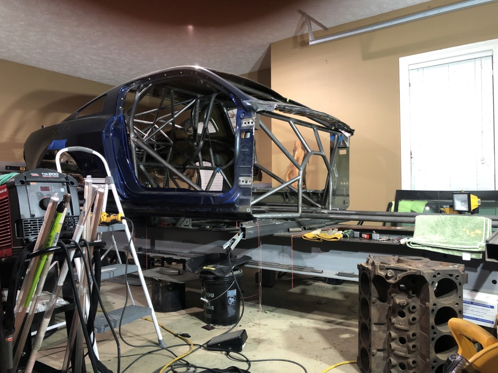
Next on the agenda is engine mounting. AFter talking w/ several guys, it was settled that the rear axle centerline to back of the block dimension needed to be around 82-82.5" and most wanted the crank centerline about 10-10.5" off the track surface. So, I pulled out the trusty spare CJ block I have for mock-up purposes.
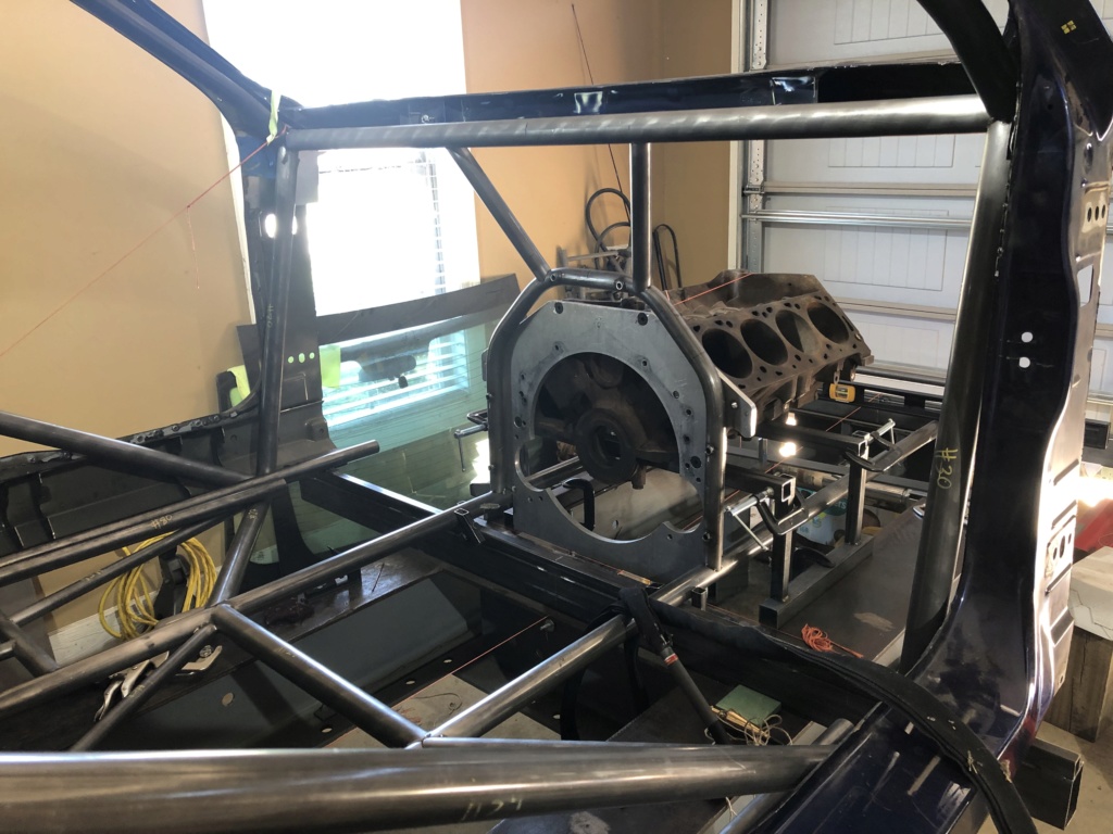
This project has come with the fabrication of many jigs! As you can see under the block, I built a small jig out of square tubing to help hold the block at the correct height and pitch. The engine ended up sloping downhill in the front about 1.5* since the pinion is going to be higher than the crank centerline.
Also the midplate in the pic is an old midplate for another car, but it served as a great template for Keith Fulp!
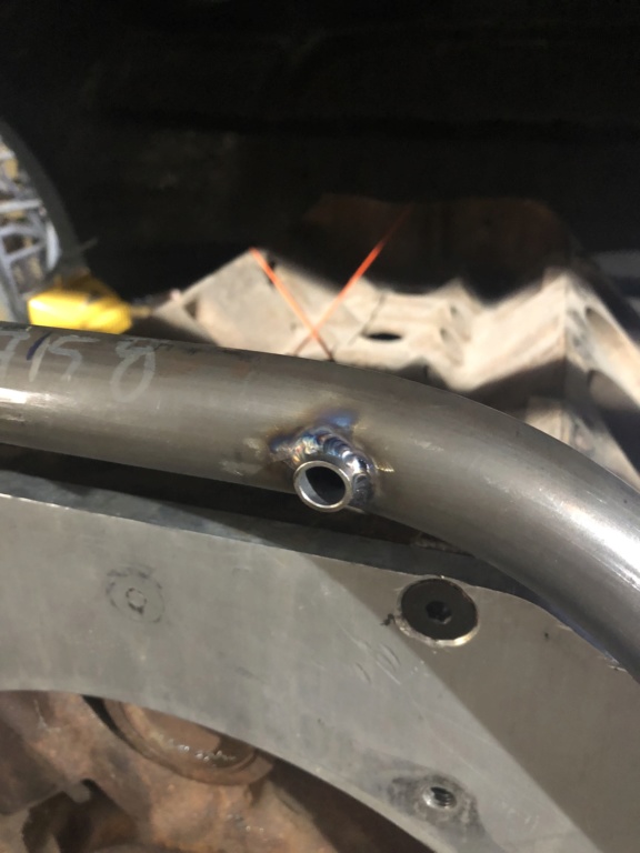
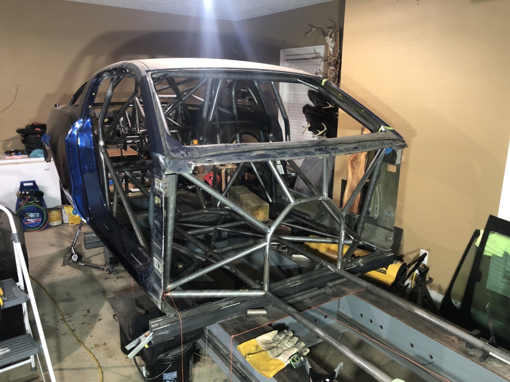
Midplate hoop in place and supporting bars. One cool detail here was that I ended up offset notching all of the bars from the dash etc down to the midplate hoop to the front side. This will allow for flush mounting of the firewall when I get there! Oh- and I decided that the car would pretty much always have fender exit headers, so the bottom bar in the pic is parallel with the ground instead of kicked up on the side to allow for chassis exit headers. This will allow me to have a flat floor as well.
Next on the agenda is engine mounting. AFter talking w/ several guys, it was settled that the rear axle centerline to back of the block dimension needed to be around 82-82.5" and most wanted the crank centerline about 10-10.5" off the track surface. So, I pulled out the trusty spare CJ block I have for mock-up purposes.

This project has come with the fabrication of many jigs! As you can see under the block, I built a small jig out of square tubing to help hold the block at the correct height and pitch. The engine ended up sloping downhill in the front about 1.5* since the pinion is going to be higher than the crank centerline.
Also the midplate in the pic is an old midplate for another car, but it served as a great template for Keith Fulp!


Midplate hoop in place and supporting bars. One cool detail here was that I ended up offset notching all of the bars from the dash etc down to the midplate hoop to the front side. This will allow for flush mounting of the firewall when I get there! Oh- and I decided that the car would pretty much always have fender exit headers, so the bottom bar in the pic is parallel with the ground instead of kicked up on the side to allow for chassis exit headers. This will allow me to have a flat floor as well.

460bronco- Posts : 364
Join date : 2010-04-07
Age : 38
Location : Meridian, Ms

460bronco- Posts : 364
Join date : 2010-04-07
Age : 38
Location : Meridian, Ms
 Re: 2012 Mustang 25.1 chassis build
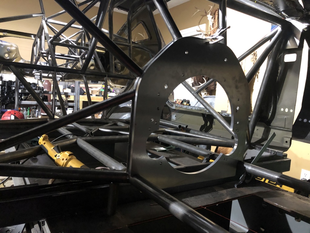
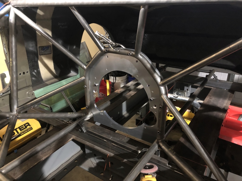
Big shout out to Keith Fulp here! Sorry these pics aren't the best quality, but he absolutely knocked it out of the park on my custom midplate project. Excellent guy to work with.
The midplate has the option of running the starter in the stock location or on the other side. Mine will utilize the driver side for now due to kick-out on the oilpan is on the passenger side.
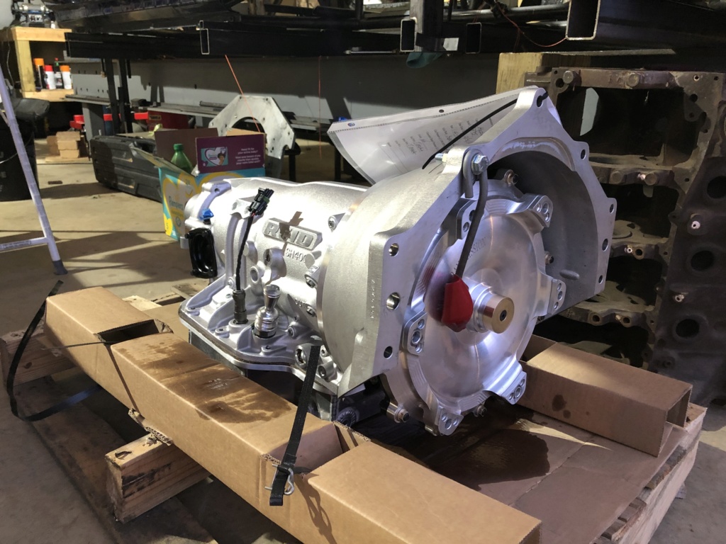
I ended up deciding to go with a turbo 400 trans, so this midplate will serve as an adapter to go from ford to chevy pattern.


460bronco- Posts : 364
Join date : 2010-04-07
Age : 38
Location : Meridian, Ms
 Re: 2012 Mustang 25.1 chassis build
Ok- So this is where the project gets very interesting again! Setting up the struts!!!
I ended up going w/ a 17" spindle mount wheel from RC Components and that has a corresponding 26" tire. Most Chassis cars have traditionally ran a 15" front wheel w/ corresponding 25" tire. If you want to switch back and forth, this creates a problem!
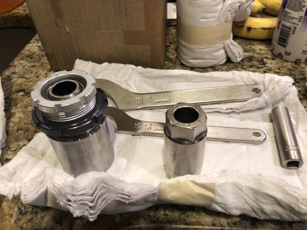
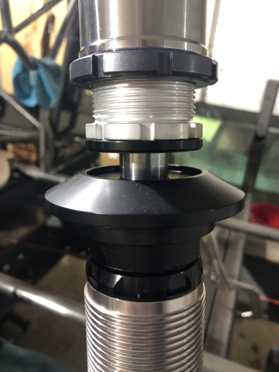
In the photo below, you can see that I picked up some adjustable strut cups. These are really nice units that will allow for ride height changes without changing how much shaft is sticking out of the strut. These are from lamb and have a spherical bearing that the top of the strut mounts in to prevent any binding throughout the range of motion.
Next comes my strut Jig-
I decided that I wanted the car to have 1" stagger from driver to passenger side wheelbase and had to figure out how to hold the struts in position while mounting the upper strut cup. So, I took some 2x3 rectangular tubing and had a friend of mine bore the tubing to match the bearing race dimensions on the spindle. We also squared up the end of the tubing to keep everything nice and true.
So, In the photo below the spindle pierces the jig at the final ride height that will be achieved with the wheel. The holes the spindle pierces in the jig are parallel to the ground and set the camber at 0*.
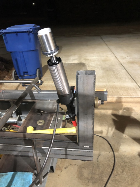
Another angle of the strut jig. In this photo, you can see my angle finder on the steering arm with the strut mounted at 10* Caster.

I ended up going w/ a 17" spindle mount wheel from RC Components and that has a corresponding 26" tire. Most Chassis cars have traditionally ran a 15" front wheel w/ corresponding 25" tire. If you want to switch back and forth, this creates a problem!
In the photo below, you can see that I picked up some adjustable strut cups. These are really nice units that will allow for ride height changes without changing how much shaft is sticking out of the strut. These are from lamb and have a spherical bearing that the top of the strut mounts in to prevent any binding throughout the range of motion.

Next comes my strut Jig-
I decided that I wanted the car to have 1" stagger from driver to passenger side wheelbase and had to figure out how to hold the struts in position while mounting the upper strut cup. So, I took some 2x3 rectangular tubing and had a friend of mine bore the tubing to match the bearing race dimensions on the spindle. We also squared up the end of the tubing to keep everything nice and true.
So, In the photo below the spindle pierces the jig at the final ride height that will be achieved with the wheel. The holes the spindle pierces in the jig are parallel to the ground and set the camber at 0*.

Another angle of the strut jig. In this photo, you can see my angle finder on the steering arm with the strut mounted at 10* Caster.


460bronco- Posts : 364
Join date : 2010-04-07
Age : 38
Location : Meridian, Ms
 Re: 2012 Mustang 25.1 chassis build
I needed a good way to hold the caster @ 10* while fitting the bars to lock in the caster and camber. AFter a little thinking I came up with this idea.
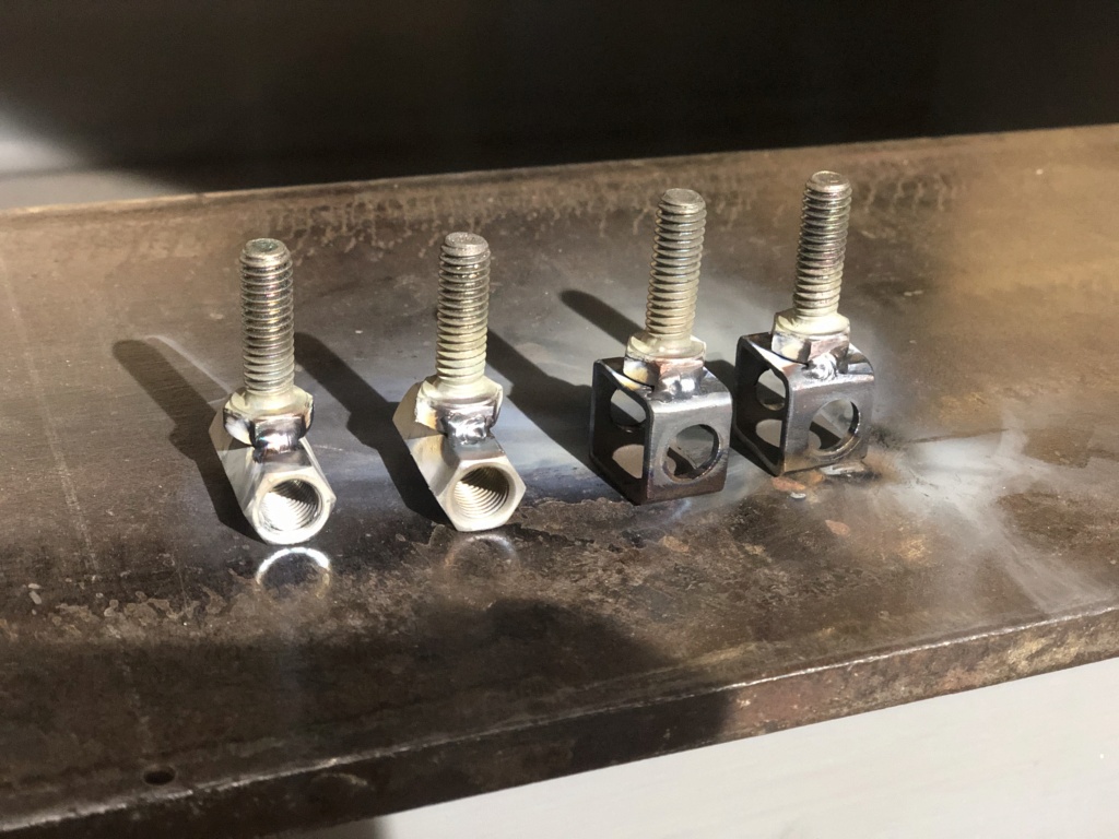

After assembling the assortment of rod couplings/bolts, nuts and all thread rod, I came up with a way to precisely adjust the caster, but also a way to firmly hold it in place while fitting the bars to the strut cups.
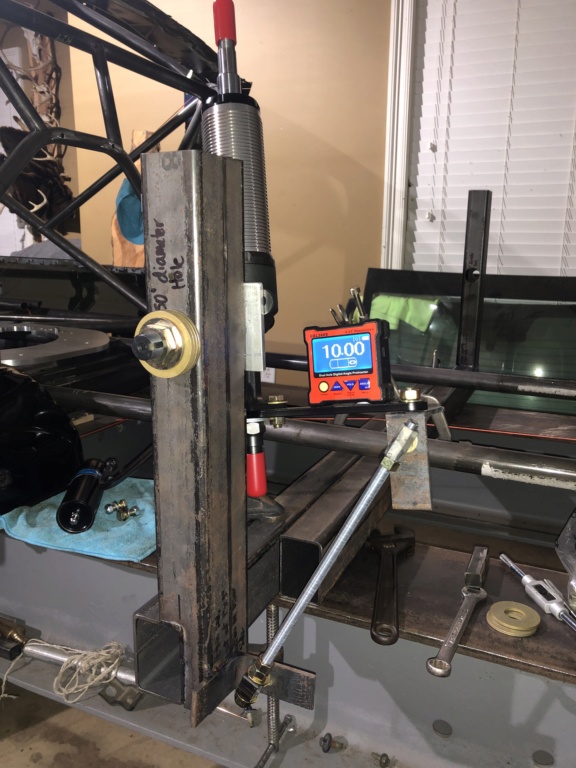


After assembling the assortment of rod couplings/bolts, nuts and all thread rod, I came up with a way to precisely adjust the caster, but also a way to firmly hold it in place while fitting the bars to the strut cups.


460bronco- Posts : 364
Join date : 2010-04-07
Age : 38
Location : Meridian, Ms
 Re: 2012 Mustang 25.1 chassis build
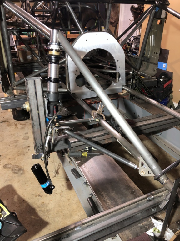
Here's a close-up shot of the adjustable strut cup. Menscer wanted about 1/2" of shaft available for compression at ride height, so I ended up finding some washers that fit perfectly in the top spring retainer and around the shaft. They can be seen in the bottom photo (They are gold in color).
Lower control arm kit from strange went in without a hitch. Mounting points were determined and fit, then the tubing cut to length and tac'd into place. The control arm tubes utilize a weld all the way around the tubing adapter for the heim joint as well as a few plug welds.
And- Here is a much better shot of the beautiful midplate by Keith Fulp!


460bronco- Posts : 364
Join date : 2010-04-07
Age : 38
Location : Meridian, Ms
 Re: 2012 Mustang 25.1 chassis build
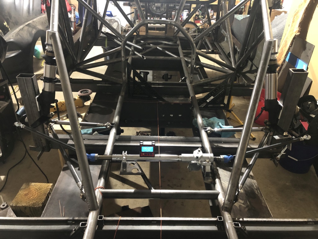
Flaming river rack installed. I picked this one up from Tim Mcamis as well as their billet mounting brackets. I can get a better pick if someone is interested. In this pic I haven't cut down the tie-rod ends to proper length yet.
Here is a side shot of my Anti-Roll Bar and mounting location. Once again I got to use my adjustable jig from the beginning of the build to hold the ARB horizontal and centered while mounting to the chassis. (See the C-clamp and v-block in the background).
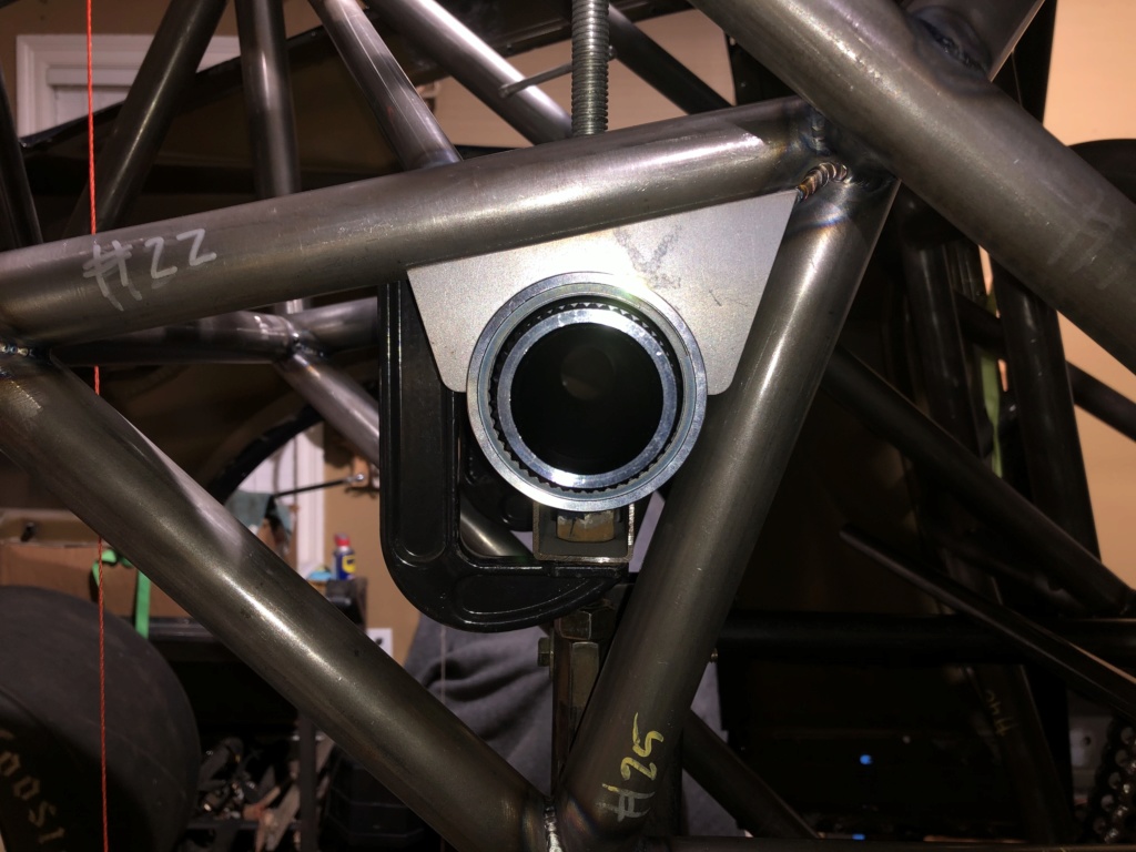
Final product on Anti-Roll Bar mounting. This anti-roll comes from Tim McAmis also and consists of a 300M HD splined shaft. It utilizes splined Nylon bearings within the housings to prevent binding.
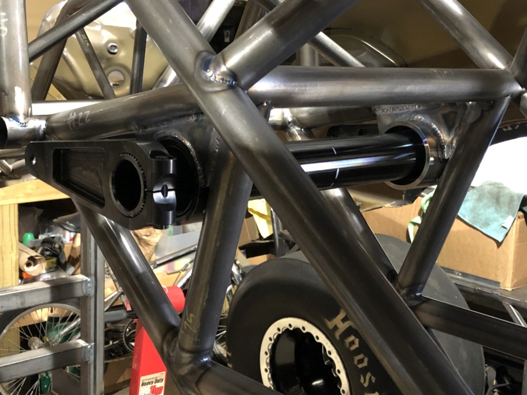

Here is a side shot of my Anti-Roll Bar and mounting location. Once again I got to use my adjustable jig from the beginning of the build to hold the ARB horizontal and centered while mounting to the chassis. (See the C-clamp and v-block in the background).

Final product on Anti-Roll Bar mounting. This anti-roll comes from Tim McAmis also and consists of a 300M HD splined shaft. It utilizes splined Nylon bearings within the housings to prevent binding.


460bronco- Posts : 364
Join date : 2010-04-07
Age : 38
Location : Meridian, Ms

460bronco- Posts : 364
Join date : 2010-04-07
Age : 38
Location : Meridian, Ms
 Re: 2012 Mustang 25.1 chassis build
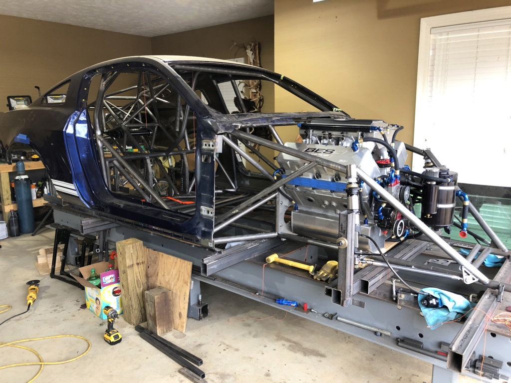
Side profile shot after finishing up strut mounting.
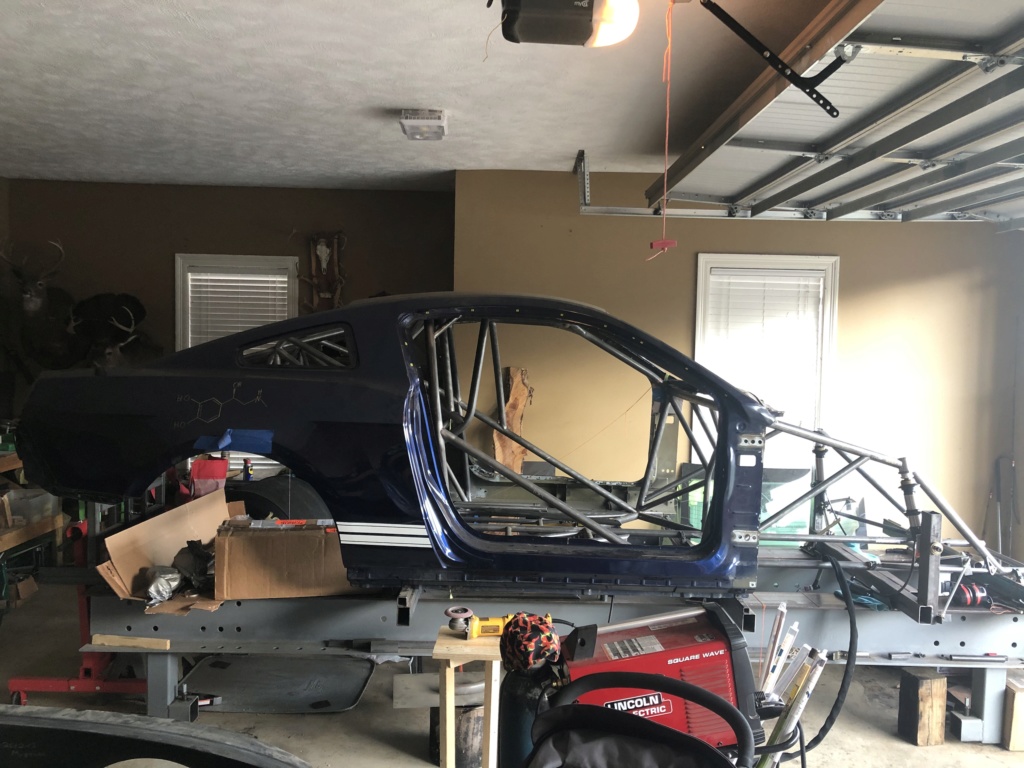
And this brings us to the current status of the project. Engine was mocked up to fine tune frame upright position for the front plate. Can't wait to get this thing off the jig!!!
The last few things to finish up will be the double frame rail in the driver compartment as well as the door x's. I have them fitted, but just haven't welded them in yet because I'm still jumping in and out of the car quite a bit.


460bronco- Posts : 364
Join date : 2010-04-07
Age : 38
Location : Meridian, Ms
 Re: 2012 Mustang 25.1 chassis build
Looking great keep posting pictures when you get them!! 
Mark Miller- Posts : 1928
Join date : 2009-09-01
 Re: 2012 Mustang 25.1 chassis build
Hello, thisnis a great looking build. Out of curiosity I'm trying to start my own chassis build soon and was wondering how much tubing it actually takes. If you have an idea of what this project used, or even just what a 10 point cage takes that would be very helpful. Thanks
Seth
Seth
litshoot- Posts : 101
Join date : 2015-09-11
Location : Sfl
 Re: 2012 Mustang 25.1 chassis build
litshoot wrote:Hello, thisnis a great looking build. Out of curiosity I'm trying to start my own chassis build soon and was wondering how much tubing it actually takes. If you have an idea of what this project used, or even just what a 10 point cage takes that would be very helpful. Thanks
Seth
I bought this in a kit from Chassis Engineering, so I'm not real sure exactly how much tubing is in the thing, but it does consist of 1-5/8, 1-1/2, 1-1/4, 1", 3/4, and some 5/8' tubing.

460bronco- Posts : 364
Join date : 2010-04-07
Age : 38
Location : Meridian, Ms
 Re: 2012 Mustang 25.1 chassis build
Mark Miller wrote:Looking great keep posting pictures when you get them!!
Thanks Mark! I've got to get better about that!

460bronco- Posts : 364
Join date : 2010-04-07
Age : 38
Location : Meridian, Ms
Page 3 of 3 •  1, 2, 3
 Similar topics
» Mustang II tube chassis build
» My new 528 combo
» Need a Chassis for my new build. GOT ONE!!!
» chassis build or buy
» C460 headers, possibly a460 too
» My new 528 combo
» Need a Chassis for my new build. GOT ONE!!!
» chassis build or buy
» C460 headers, possibly a460 too
Page 3 of 3
Permissions in this forum:
You cannot reply to topics in this forum|
|
|

